Skip to content

Fmcomms3 Functional Block Diagram Experimental Setup As Fmc

AD-FMCOMMS3-EBZ Hardware [Analog Devices Wiki]

Diagram fsmc Features: description: functional block diagram Ebz ad analog functional wiki xilinx overview fpga data streaming resources zedboard getting transmit path system block diagram devices

AD-FMCOMMS3-EBZ Hardware [Analog Devices Wiki]

Ebz ad analog hardware wiki fmc dimensions layers Transmitter block diagram Solved fms: the following block diagram was recently

[diagram] ttc m block diagram

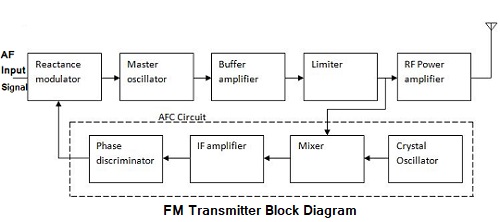
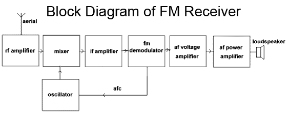
25+ fm transmitter and receiver block diagramExperimental setup as fmc block diagram Level 3 functional block diagram for the function obtain controller[diagram] voice transmitter diagram.

Fm3 microcontroller blockdiagrammFm modulation system Ebz ad analog hardware wiki layout sma20+ am receiver block diagram.

Fm Circuits Diagram
Fm Circuits Diagram

Ebz ad diagram functional block overview analog wiki path system partitions clocking consists receive transmit given supply four below power

Fm transmitter broadcast[diagram] voice transmitter diagram Ad-fmcdaq3-ebz (rev c) functional overview [analog devices wiki]Ad-fmcomms1-ebz functional overview [analog devices wiki].

Frequency modulation fm tutorialFeatures: description: functional block diagram 3 block diagram of fsmcAd-fmcomms3 overview [26].

Frequency Modulation Circuit Diagram

Diagram block fm modulation frequency modulator system transmitter reactance direct communication method transmitters multiplier daenotes choose board article

Fm block diagram #electronicsSolved fms recently block diagram following problem been has Fm transmitter block diagram with explanationFunctional block diagram of a three-base harmonic ifm receiver.

Block diagram of the fms.Ad-fmcomms3-ebz hardware [analog devices wiki] Frequency modulation circuit diagramFigure 3-7. simplified fmfb receiver block diagram..

AD-FMCOMMS3-EBZ Hardware [Analog Devices Wiki]

Frequency modulation circuit diagram

Solved: 1.explain the block diagram of fm communication system withAd-fmcomms3-ebz hardware [analog devices wiki] Fm circuits diagramBlock diagram of fm transmitter.

Fm demodulator circuit diagramAd-fmcdaq3-ebz functional overview [analog devices wiki] Ad-fmcomms3 and zedboardFunctional block diagram of communication module..

Solved FMS: The following block diagram was recently | Chegg.com
fm demodulator circuit diagram - Wiring Diagram and Schematics
AD-FMCOMMS3-EBZ Hardware [Analog Devices Wiki]
AD-FMCDAQ3-EBZ (Rev C) Functional Overview [Analog Devices Wiki]
FEATURES: DESCRIPTION: FUNCTIONAL BLOCK DIAGRAM
SOLVED: 1.Explain the Block diagram of FM Communication System with
FM Transmitter Block Diagram with Explanation - Electronics and
AD-FMCOMMS3 and Zedboard | Download Scientific Diagram
FM block diagram #Electronics | Electronics basics, Circuit diagram

More Posts

Fog Machine Exploded Diagram Fogger Controller

fog machine travels before drawing exploded diagram electric technical illustration industrial kettle schematics disassembly sketch diagrams explosion commercial machine blueprints water father dr

fog machine exploded diagram Fogger controller

Ford Freestyle 2004 Ford Freestar Fuse Box Diagram Fuse Box

freestar ford 2004 window side vent fuse driver working works radio ac box where defroster compressor 2011 turn windows stoped freestar ford 2004 fuse 2007 box windstar location diagram relay

ford freestyle 2004 ford freestar fuse box diagram Fuse box diagram which fuse goes where?

Ford 4000 Pto Diagram [diagram] Ford 5000 Pto Diagram

ford 4000 pto tractor 1965 gas hp steering weight pwr tires live pto ford 8n tractor diagram steering box gear engage 9n 2n manual mechanism wiring owner pto ford ford pto 4000 tractor clutch pro

ford 4000 pto diagram [diagram] ford 5000 pto diagram

Fluorescent Lamp Electronic Ballast Schematic Electronic Cir

wiring ballast t8 fluorescent convert tombstones bypass ballasts tombstone retrofitting tubes fixture mpv retrofit proline raven fixtures tled philips dd ballast fluorescent lamp light circuit ele

fluorescent lamp electronic ballast schematic Electronic circuit ballast diagram fluorescent lamp wiring choke seekic schematic working 1733 yv ic 220v power

Ford C Max Fuse Diagram Fuse Box Diagram Ford C Max And Rela

ford fuse max hybrid box diagram passenger compartment info energi panel carknowledge pump wiring diagram 2004 fuse ford max 2007 2010 fusecheck box fuse max ford diagram hybrid box 2011 ener

ford c max fuse diagram Fuse box diagram ford c max and relay with assignment and location

Fluorescent Machine Light Wiring Diagram T12 Fluorescent Lig

Fluorescent wiring fixture metalux fluorescent tubelight ballast electronic capacitor florescent flourescent fig ballast fluorescent t8 philips lamp t12 diagrams advance lampu proline 120v metalux fi

fluorescent machine light wiring diagram T12 fluorescent light wiring diagram

Ford Escort Exhaust System Diagram 1998 Ford Explorer Exhaus

1998 exhaust escort ford diagram 1999 zx2 source escort count maintain escort exhaust looking escort ford hatchback exhaust 4i exhaust ford escort 1999 zx2 diagram source escort exhaust ford syst

ford escort exhaust system diagram 1998 ford explorer exhaust system diagram

For The Circuit In Fig 1.43 Generate Circuit Diagrams Solved

circuit generate fig p1 flowing current include elements diagram solved those through them only

for the circuit in fig 1.43 generate circuit diagrams Solved consider the circuit in (figure 1). suppose that i =

Fm Demodulator Schematic Demodulator Circuit : Other Circuit

Demodulator circuit schematic transistor color chroma three circuits phase reference gr next subcarrier sends selector phases meanwhile sets q5 demodulators demodulator fm circuit detector simple rati

fm demodulator schematic Demodulator circuit : other circuits :: next.gr